▷ Arm Cortex-M4 (3): I2C


Arm Cortex-M4 (3): I2C

  • ✅ practice description:
    • The I2C (Inter-Integrated Circuit) practice using the NUCLEO-F446RE Development Board and STM32CubeIDE is an educational and hands-on experience that allows electronics and programming enthusiasts to delve into the exciting world of serial communications in embedded systems. I2C is a widely used serial communication protocol for connecting different components on a development board, enabling efficient and reliable communication between them.
  • ✅ I2C in Brief
    • I2C, which stands for Inter-Integrated Circuit, is a serial communication protocol that was originally designed by Philips Semiconductor in 1982. Over the years, it has evolved and become a de facto standard for communication between components in embedded systems. Although conceived several decades ago, it remains a relevant technology today due to its simplicity and versatility.
  • ✅ Basic Principles of I2C
    • I2C operates based on a pair of communication wires: one for data transmission (SDA) and another for clock synchronization (SCL). This allows bidirectional communication between multiple devices connected on the same bus. The key feature of I2C is its ability to connect multiple devices on a single bus, each with a unique address, making it ideal for embedded systems with multiple peripherals.
  • ✅ Development with NUCLEO-F446RE and STM32CubeIDE
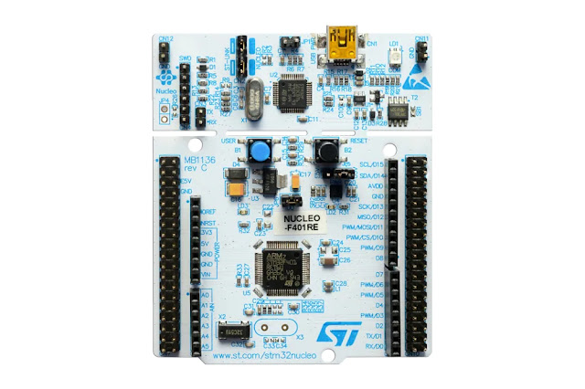
    • The NUCLEO-F446RE Development Board is a high-performance development platform based on the STM32F446RE microcontroller from STMicroelectronics. STM32CubeIDE is an integrated development environment that facilitates programming and debugging of STM32 microcontrollers. Together, they form a powerful combination for learning and working with I2C.
    • In this practice, you will learn to configure and use the I2C protocol on the NUCLEO-F446RE using STM32CubeIDE. You will be able to connect different devices such as sensors, OLED displays, or EEPROM memory modules through the I2C bus and write code to communicate with them efficiently. Furthermore, you will learn how to debug and verify communication to ensure everything works correctly.
  • ✅ Steps:
    • Selection of the STM32F446RE Development Board.

  • Including the .h files of the devices and drivers.
  • Write the main code to be used.⭐
    #include <II2C.h>
    #include <stdint.h>
    #include <stdio.h>
    #include "STM32F446xx.h"
    #include "usart.h"
    #include "adxl345-2.h"
    //#include "stm32f4.h"
    char key;
    int16_t x,y,z;
    float xg,yg,zg;
    extern uint8_t data_rec[6];
    //const float FOUR_G_SCALE_FACT = 0.0078;
    ////////////////////////////Programa general
    int main (void)
    {
    //I2C
    aadxl_init();
    while(1)
    {
    aadxl_read_values(DATA_START_ADDR);
    x = ((data_rec[1]<<8) | data_rec[0]);
    y = ((data_rec[3]<<8) | data_rec[2]);
    z = ((data_rec[5]<<8) | data_rec[4]);
    xg = (x*0.0078);
    yg = (y*0.0078);
    zg = (z*0.0078);
    }
    //USART
    /*
    uart2_tx_init();
    while(1)
    {
    key = uart2_read();
    if (key == '1')
    {
    uart2_write('C');
    for (int var = 0; var < 100000; ++var)
    {
    }
    }
    }
    */
    /////////////////////////////////////////////
    /*while(1)
    {
    uart2_write('C');
    for (int var = 0; var < 100000; ++var)
    {
    }
    }*/
    }
    view raw gistfile1.txt hosted with ❤ by GitHub

  • Write the .h and .c files
    #include <II2C.h>
    #define GPIOBEN (1U<<1)
    #define I2C1EN (1U<<21)
    #define I2C_100KHz 80 //APB1 A 16MHZ for standard mode
    //#define I2C_400KHz 20 //APB1 A 16MHZ for fast mode
    //#define I2C_100KHz 10 //APB1 A 2MHZ
    #define MD_max_rise_time 17
    #define CR1_PE (1U<<0)
    #define SR2_BUSY (1U<<1)
    #define CR1_START (1U<<8)
    #define SR2_BUSY (1U<<1)
    #define CR1_START (1U<<8)
    #define SR1_SB (1U<<0)
    #define SR1_ADDR (1U<<1)
    #define SR1_TXE (1U<<7)
    #define CR1_ACK (1U<<10)
    #define CR1_STOP (1U<<9)
    #define SR1_RXNE (1U<<6)
    #define SR1_BTF (1U<<2)
    /*
    * Alternate function
    * PB8 --- SCL
    * PB9 --- SDA
    * */
    void II2C1_init(void)
    {
    //Enable clock I2C1
    //PB8 and PB9 mode to alternate function
    //PB8 and PB9 output type open drain
    //PB8 and PB9 enable pull up
    //Enable clock access to GPIOB*/
    RCC -> AHB1ENR |=GPIOBEN;
    /*Set PB8 and PB9 mode to alternate function*/
    //Table 11. Alternate function (continued)
    GPIOB->MODER &=~(1U<<16);
    GPIOB->MODER |=(1U<<17);
    GPIOB->MODER &=~(1U<<18);
    GPIOB->MODER |=(1U<<19);
    /*Set PB8 and PB9 output type to open drain*/
    GPIOB->OTYPER |=(1U<<8);
    GPIOB->OTYPER |=(1U<<9);
    /*Enable Pull-up for PB8 and PB9*/
    GPIOB->PUPDR |=(1U<<16);
    GPIOB->PUPDR &=~(1U<<17);
    GPIOB->PUPDR |=(1U<<18);
    GPIOB->PUPDR &=~(1U<<19);
    //
    GPIOB->AFR[1] &= ~(1U<<0);
    GPIOB->AFR[1] &= ~(1U<<1);
    GPIOB->AFR[1] |= (1U<<2);
    GPIOB->AFR[1] &= ~(1U<<3);
    GPIOB->AFR[1] &= ~(1U<<4);
    GPIOB->AFR[1] &= ~(1U<<5);
    GPIOB->AFR[1] |= (1U<<6);
    GPIOB->AFR[1] &= ~(1U<<7);
    /*Enable clock access to I2C1*/
    RCC->APB1ENR |= I2C1EN;
    //Slave mode peripherial
    I2C1-> CR1 |= (1U<<15);
    I2C1-> CR1 &= ~(1U<<15);
    I2C1-> CR2 = (1U<<4); //16MHZ
    //24.6.8 I2C clock control register (I2C_CCR)
    I2C1-> CCR = I2C_100KHz;
    //Ser rise time
    I2C1-> TRISE = MD_max_rise_time;
    //enable I2C1 modeule
    I2C1-> CR1 |= CR1_PE;
    }
    void II2C1_byteRead(char saddr, char maddr, char* data)
    {
    volatile int tmp;
    /* Wait until bus not busy */
    while (I2C1->SR2 & (SR2_BUSY)){}
    /* Generate start */
    I2C1->CR1 |= CR1_START;
    /* Wait until start flag is set */
    while (!(I2C1->SR1 & (SR1_SB))){}
    /* Transmit slave address + Write */
    I2C1->DR = saddr << 1;
    /* Wait until addr flag is set */
    while (!(I2C1->SR1 & (SR1_ADDR))){}
    /* Clear addr flag */
    tmp = I2C1->SR2;
    /* Send memory address */
    I2C1->DR = maddr;
    //Wait until transmitter empty
    while (!(I2C1->SR1 & SR1_TXE)){}
    /*Generate restart */
    I2C1->CR1 |= CR1_START;
    /* Wait until start flag is set */
    while (!(I2C1->SR1 & SR1_SB)){}
    //Transmit slave address + READ
    I2C1 ->DR= saddr <<1 | 1;
    while(!(I2C1->SR1 & SR1_ADDR)){}
    //Disa8le acknowledga
    I2C1 -> CR1 &= ~CR1_ACK;
    //Clear addr flag
    tmp = I2C1 -> SR2;
    //Generate Stop after data received
    I2C1 -> CR1 |= CR1_STOP;
    while(!(I2C1->SR1 & SR1_RXNE)){}
    //Read data from DR
    *data++ = I2C1->DR;
    }
    void II2C1_burstRead(char saddr, char maddr, int n, char* data)
    {
    volatile int tmp;
    /* Wait until bus not busy */
    while (I2C1->SR2 & (SR2_BUSY)){}
    /* Generate start */
    I2C1->CR1 |= CR1_START;
    /* Wait until start flag is set */
    while (!(I2C1->SR1 & SR1_SB)){}
    /* Transmit slave address + Write */
    I2C1->DR = saddr << 1;
    /* Wait until addr flag is set */
    while (!(I2C1->SR1 & SR1_ADDR)){}
    /* Clear addr flag */
    tmp = I2C1->SR2;
    /* Wait until transmitter empty */
    while (!(I2C1->SR1 & SR1_TXE)){}
    /*Send memory address */
    I2C1->DR = maddr;
    /*Wait until transmitter empty */
    while (!(I2C1->SR1 & SR1_TXE)){}
    /*Generate restart */
    I2C1->CR1 |= CR1_START;
    //wait until start flag is set
    while (!(I2C1->SR1 & SR1_SB)){}
    //transmit slave address + Read
    I2C1->DR = saddr << 1 | 1;
    //wait until addr flag is set
    while (!(I2C1->SR1 & SR1_ADDR)){}
    //clear addr flag
    tmp = I2C1 ->SR2;
    //Enable acknowledge
    I2C1 -> CR1 |= CR1_ACK;
    while (n > 0U)
    {
    /*if one byte*/
    if(n == 1U)
    {
    /* Disable Acknowledge */
    I2C1-> CR1 &= ~CR1_ACK;
    /* Generate Stop */
    I2C1-> CR1 |= CR1_STOP;
    /* Wait for RXNE flag set */
    while (!(I2C1->SR1 & SR1_RXNE)){}
    /* Read data from DR */
    *data++ = I2C1->DR;
    break;
    }
    else
    {
    /* Wait until RXNE flag is set */
    while (!(I2C1->SR1 & SR1_RXNE)){}
    /* Read data from DR +*/
    (*data++) = I2C1->DR;
    n--;
    }
    }
    }
    void II2C1_burstWrite(char saddr, char maddr, int n, char* data)
    {
    volatile int tmp;
    /* Wait until bus not busy */
    while (I2C1->SR2 & (SR2_BUSY)){}
    /* Generate start */
    I2C1->CR1 |= CR1_START;
    /* Wait until start flag is set */
    while (!(I2C1->SR1 & (SR1_SB))){}
    /* Transmit slave address */
    I2C1->DR = saddr << 1;
    /* Wait until addr flag is set */
    while (!(I2C1->SR1 & (SR1_ADDR))){}
    /* Clear addr flag */
    tmp = I2C1->SR2;
    /* Wait until data register empty */
    while (!(I2C1->SR1 & (SR1_TXE))){}
    /* Send memory address */
    I2C1->DR = maddr;
    for (int i = 0; i< n; i++) {
    /* Wait until data register empty */
    while (!(I2C1->SR1 & (SR1_TXE))){}
    //transmit memory address
    I2C1-> DR = *data++;
    }
    //wait memory address
    while (!(I2C1->SR1 & (SR1_BTF))){}
    //Generate stop
    I2C1->CR1 |= CR1_STOP;
    }


  • Compile, debug and testing.

  • ✅ Conclusion
    • In summary, the I2C practice with the NUCLEO-F446RE Development Board and STM32CubeIDE will provide you with valuable experience in the world of serial communication in embedded systems. I2C is a versatile and widely used protocol that remains relevant today, and learning to work with it will open doors to a wide range of electronic applications. This exercise will help you understand the fundamentals of I2C and acquire practical skills in STM32 microcontroller programming, which are essential in the field of electronics and automation.
Comments

Popular posts from this blog

▷ Arm Cortex-M4 (2): ADC

    Arm Cortex-M4 (2): ADC  ➡️ #EmbeddedSystems #ARM #CortexM4 #CProgrammingLanguage #ADC #ADC_read #Nucleo # F446RE #STM32F446RE #MCU #STM32cube ⭐ Codes of practice:  https://github.com/vasanza/STM32/tree/main/4_adc_nucleo ⭐ Repository with more examples:  https://github.com/vasanza/STM32/tree/main ✅  Developed by:  John Rivera Burgos ➡️ Device: Development Board:  NUCLEO-F446RE Processor:  STM32F446RE MCU, Arm® Cortex®-M4 core at 180 Mhz. ➡️ Compiler: STM32CubeIDE ⭐ Device provided by: EcuaPlus ⭐ When using this resource, please cite the original publication: Avilés-Mendoza, K., Gaibor-León, N. G., Asanza, V., Lorente-Leyva, L. L., & Peluffo-Ordóñez, D. H. (2023). A 3D Printed, Bionic Hand Powered by EMG Signals and Controlled by an Online Neural Network.  Biomimetics, 8(2), 255. ✅ practice description: It serves to convert an analog signal (voltage or current-based) into a digital signal, in order to facilitate its proce...

▷ Visualización de datos: de Temperatura, Humedad y Temp de CPU.

  Para esta publicación, se han instalado dos sensores para la recolección de datos en tiempo real, los cuales están actualmente en funcionamiento en la ciudad de Guayaquil: uno para medir la humedad y otro para medir la temperatura. Ambos sensores utilizan tecnología LoRA para enviar la información recopilada a un Gateway. Este Gateway actúa como punto central de conexión, recibiendo los datos de los sensores y enviándolos a la plataforma de Google Cloud a través de una conexión celular LTE. Una vez que los datos están almacenados en la plataforma de Google Cloud, se ha creado una interfaz web personalizada. Esta interfaz permite la visualización y el análisis de los datos recolectados por los sensores, ofreciendo una representación clara y fácilmente accesible para los usuarios. Leaflet viewer with OpenStreetMap Leaflet viewer with OpenStreetMap En este post, vamos a explorar cómo visualizar datos en tiempo real provenientes de Google Cloud utilizan...

▷ Visualización de ultimas 24h de Temperatura, Humedad y Temp. CPU

Para esta publicación, se han instalado dos sensores para la recolección de datos en tiempo real, los cuales están actualmente en funcionamiento en la ciudad de Guayaquil: uno para medir la humedad y otro para medir la temperatura. Ambos sensores utilizan tecnología LoRA para enviar la información recopilada a un Gateway. Este Gateway actúa como punto central de conexión, recibiendo los datos de los sensores y enviándolos a la plataforma de Google Cloud a través de una conexión celular LTE. Una vez que los datos están almacenados en la plataforma de Google Cloud, se ha creado una interfaz web personalizada. Esta interfaz permite la visualización y el análisis de los datos recolectados por los sensores, ofreciendo una representación clara y fácilmente accesible para los usuarios. Leaflet viewer with OpenStreetMap Leaflet viewer with OpenStreetMap En el mundo interconectado de hoy, la capacidad de recopilar y visualizar datos en tiempo real ...

▷ Arm Cortex-M4 (1): USART serial communication

  Arm Cortex-M4 (1): USART serial communication  ➡️ #EmbeddedSystems #ARM #CortexM4 #CProgrammingLanguage #USART #Nucleo # F446RE #STM32F446RE #MCU #STM32cube ⭐ Codes of practice:  https://github.com/vasanza/STM32/tree/main/1_usart_tx https://github.com/vasanza/STM32/tree/main/2_uart_rx_nucleo ⭐ Repository with more examples:  https://github.com/vasanza/STM32/tree/main ✅  Developed by:  John Rivera Burgos ➡️ Device: Development Board:  NUCLEO-F446RE Processor:  STM32F446RE MCU, Arm® Cortex®-M4 core at 180 Mhz. ➡️ Compiler: STM32CubeIDE ⭐ Device provided by: EcuaPlus ⭐ When using this resource, please cite the original publication: Avilés-Mendoza, K., Gaibor-León, N. G., Asanza, V., Lorente-Leyva, L. L., & Peluffo-Ordóñez, D. H. (2023). A 3D Printed, Bionic Hand Powered by EMG Signals and Controlled by an Online Neural Network.  Biomimetics, 8(2), 255. ✅ practice description: The practice of USART serial communication with the NU...